FILE 003 / DISPATCH
How to connect USB-C on your PCB — the two 5.1 kΩ resistors
4 min read
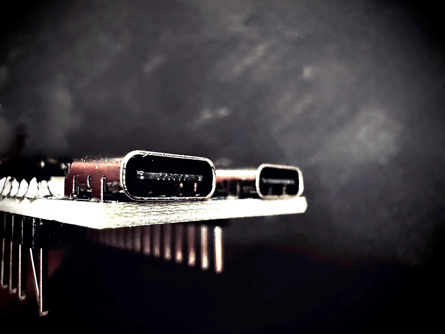
USB-C is currently the standard in the electronics world — universal, reversible, capable of transmitting both data and power. However, for a device to properly draw current from a USB-C port, two 5.1 kΩ resistors connected to the CC (Configuration Channel) lines are essential. Why are they so important, and what happens if they’re missing? Let’s find out.
What do 5.1 kΩ resistors do on CC lines?
In the USB-C connector there are two CC lines: CC1 and CC2. Their main functions are:
- Detecting the presence of a device and its orientation.
- Negotiating the power profile (how much current can flow to the device).
The 5.1 kΩ resistors, called Rd, are connected to ground on the device side (UFP — Upstream Facing Port, e.g. your PCB). On the host side (DFP — Downstream Facing Port, e.g. a computer or charger) there are pull-up resistors Rp of various values, which signal how much current the host can provide.
Why are there two CC lines instead of one?
One of USB-C’s key features is its reversibility — you can plug it in either way. This is where having two CC lines becomes essential:
- When you insert the connector one way, CC1 on the device connects to CC1 on the host.
- When you flip the connector, CC1 on the device connects to CC2 on the host (and vice versa).
By having two CC lines, the system can detect the orientation of the plug and adapt accordingly. Only one CC line is active at a time, based on the insertion orientation. This design allows for the connector’s reversibility while maintaining proper communication between devices. Without both CC lines we’d lose the ability to insert the connector either way — one of USB-C’s most convenient features.
How does current negotiation work through CC?
When a device is connected, the host detects the presence of 5.1 kΩ resistors on the CC lines. Depending on the value of its Rp resistors, the host communicates whether it can provide:
- 500 mA (default mode)
- 1.5 A
- 3.0 A
The device, by measuring the voltage on the CC line, knows how much current it can draw — and only when it detects the appropriate voltage level can it legally draw more than 500 mA.
Here is a table illustrating the voltage levels on the CC line (CC1 or CC2, depending on orientation) and the corresponding current limits:
| Current limit | Voltage | Tolerance |
|---|---|---|
| 0.5 A | 408 mV | ± 20 % |
| 1.5 A | 918 mV | ± 8 % |
| 3 A | 1.683 V | ± 8 % |
What happens if you don’t use 5.1 kΩ resistors?
The absence of these resistors means the host won’t detect the device as a USB-C power consumer. The consequences may include:
- No power at all, or a limit to very low current (typically 100 mA).
- With some cables (e.g. USB-C to USB-A), the host may not recognise the device correctly, leading to errors or a current limit of 500 mA (USB 2.0) or 900 mA (USB 3.0) — but only after proper enumeration on the data lines.
- Some chargers or hosts may not supply power at all if they don’t detect Rd resistors.
Are 5.1 kΩ resistors alone sufficient to get the full 3 A?
In theory: yes, if the power source (charger, computer) complies with the USB-C standard and declares the ability to deliver 3 A. In practice, however:
- Some chargers may limit current to 500 mA if they don’t detect negotiation on the data lines or don’t detect appropriate resistors.
- For higher voltages (above 5 V) or greater power, digital negotiation via the USB Power Delivery (PD) protocol is required.
Summary — practical tips
- Always use two 5.1 kΩ resistors to ground on the CC1 and CC2 lines in a device powered by USB-C.
- This is the simplest and cheapest way to ensure USB-C compliance and get up to 3 A at 5 V (if the source allows it).
- If your device requires more than 3 A or a higher voltage, you must implement PD negotiation.
- Lack of 5.1 kΩ resistors may result in no power, or a severe limitation of the drawn current.
For DIYers and electronics designers: don’t skimp on these two components. They determine whether your device will take full advantage of USB-C capabilities.
Sources and further reading
Main inspiration: EEVblog — How important are the two 5.1k resistors on USB-C?
- Is it sufficient to put 5.1k pulldowns on CC1 and CC2?
- Hackaday — All about USB-C: resistors and e-markers
- Hackaday — All about USB-C: example circuits
- Digi-Key — Simple way to use USB Type-C to get 5 V at up to 3 A
- Infineon — USB Type-C connector Rp, Rd and Ra termination resistors
- Faceless Tech — USB-C retrofit, 5.1k CC resistors
- Contextual Electronics — Pulling current from USB-C 5 V without negotiation